Conventional open-cut construction remains how the vast majority of pipeline mileage gets built. It is organized as a moving assembly line — a "spread" — in which specialized crews follow one another down the right-of-way, each performing one operation. Understanding the sequence matters even for trenchless specialists, because every HDD crossing ties into open-cut pipe on both ends. Here is the standard sequence for a cross-country transmission spread.
Before the Dirt Moves
Survey crews stake the right-of-way limits and centerline; utility locates are called in through 811 and verified; environmental and cultural resource inspectors flag sensitive areas per the project permits. On regulated interstate projects, construction must follow the environmental plans certificated with the project — FERC’s Upland Erosion Control, Revegetation, and Maintenance Plan and its Wetland and Waterbody Construction and Mitigation Procedures are the reference framework for most large U.S. gas projects.
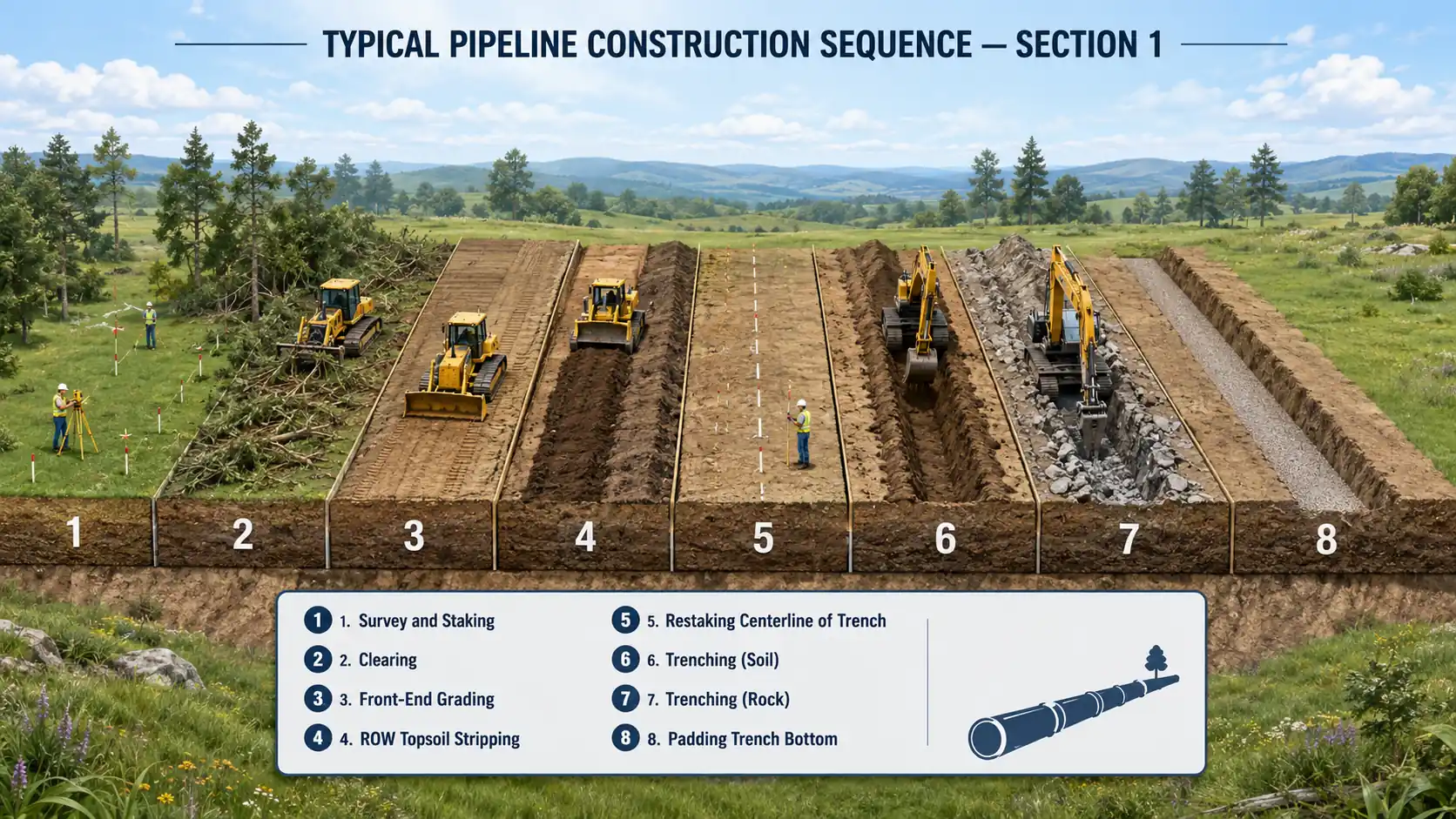
Stage 1 — Opening the Right-of-Way: Clearing, Grading, and Trenching
The first crews turn a surveyed line on a map into a workable construction corridor. Everything that follows depends on this stage being done right: topsoil segregation decides whether farmland recovers, and trench depth locks in the code cover the pipeline will live with for decades.
- Clearing and grading: vegetation is removed, topsoil is stripped and stockpiled separately (segregation is a permit requirement in agricultural land), and a level working surface is graded.
- Trenching: wheel trenchers in consistent soils, excavators in rocky or congested ground; trench depth provides the code-required cover plus pipe diameter and bedding allowance.
Stage 2 — Making the Pipe String: Stringing, Bending, and Welding
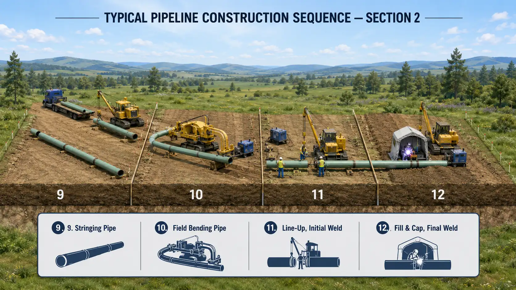
With the trench open, the fabrication crews haul pipe to the right-of-way and convert individual joints into a continuous welded string. This is the quality-critical heart of the spread — every weld placed here is about to be buried.
- Stringing: line pipe joints are hauled and laid end-to-end beside the trench, ready for the bending and welding crews that follow.
- Bending: a hydraulic bending machine puts controlled field bends in individual joints to fit vertical and horizontal alignment changes, within code limits on bend radius and ovality.
- Welding: mainline welding proceeds joint by joint (increasingly with mechanized systems); each weld is made by qualified welders under a qualified procedure per API Standard 1104.
Stage 3 — Pipe in the Ground: Inspection, Lowering-In, Backfill, Testing, and Restoration
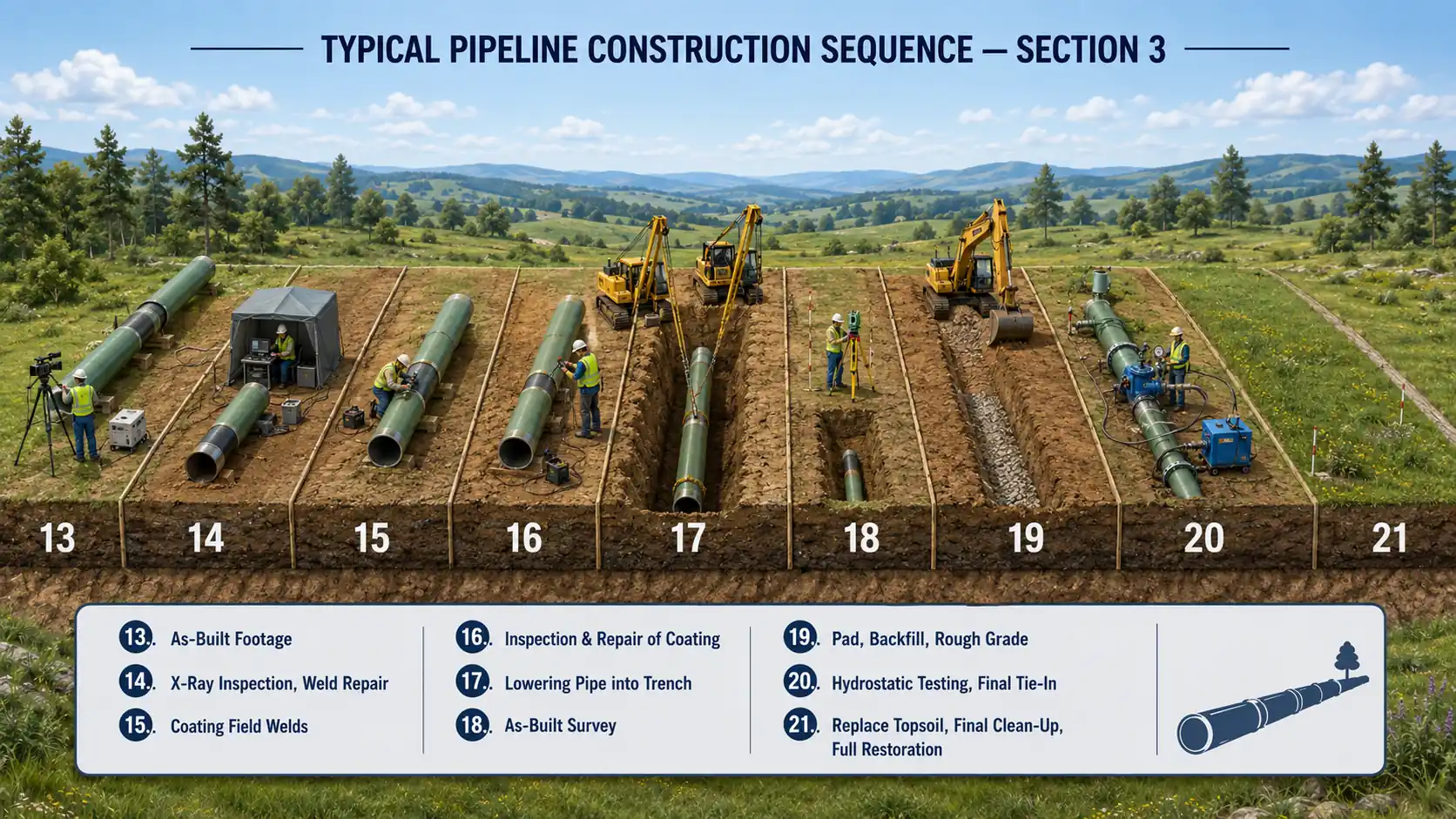
The finishing crews inspect the completed string, put it in the trench, and return the right-of-way to its owners. Lowering-in is the most delicate lift of the project — a mile of welded pipe moves from skids to trench bottom in one coordinated operation — and nothing gets buried until the welds and coating have passed their final checks.
- NDE and coating: welds are inspected — radiography or automated ultrasonic testing — then field joints are cleaned and coated, and the entire coating is holiday-tested before the pipe goes in the ground.
- Lowering-in: side-boom tractors lift the welded string and place it on the trench bottom or imported bedding/padding, controlling spans and stresses per API RP 1117 practice when existing lines are involved.
- Backfill: padding material protects the coating, spoil is returned in lifts, and compaction restores the profile; trench breakers control water migration on slopes.
- Hydrostatic testing: the completed section is filled with water and pressure-tested to the level required by 49 CFR Part 192 (gas) or Part 195 (hazardous liquids) for its class location.
- Cleanup and restoration: topsoil is replaced, contours re-established, permanent erosion controls installed, and the ROW reseeded per the landowner agreement and permits.
Where Open-Cut Meets Its Limits
The assembly line is extraordinarily efficient in open country — good spreads lay a mile or more of large-diameter pipe per day — but it stalls where the ROW is interrupted. Roads, railroads, rivers, wetlands, and congested utility corridors are handled either by specialized open-cut crossing techniques (dam-and-pump or flume crossings for smaller streams, cut-across for minor roads) or handed off to trenchless crews. The economic crossover between open-cut crossing methods and HDD is the subject of a companion article in this series.