Burial depth looks like the simplest number on a pipeline drawing, but it encodes federal code minimums, third-party damage statistics, live-load structural analysis, and future land-use judgment. The trench that provides that cover is itself a regulated, engineered excavation. This article covers how depth of cover is established for open-cut pipelines in the United States and what good trench design includes beyond depth.
Code Minimums: 49 CFR 192 and 195
For natural gas transmission lines, 49 CFR §192.327 sets minimum cover that varies with class location and material: 30 inches in normal soil for rural Class 1 locations, increasing to 36 inches in more developed class locations and at drainage ditches of public roads and railroad crossings, with reduced values (18–24 inches) permitted where excavation is in consolidated rock. For hazardous liquid pipelines, 49 CFR §195.248 follows a similar structure, requiring 36 inches in many settings, including cultivated areas — a recognition that deep tillage and drain-tile work are leading strike hazards. These are minimums at the time of construction, prudent operators add margin where erosion, scour, grading, or future development could reduce cover over the pipeline’s decades of service.
Crossings Need More Than Cover
Where a buried pipeline passes under a road or railroad, static earth load is joined by cyclic live loads from traffic. API RP 1102 provides the standard analysis for uncased steel pipeline crossings, checking cyclic stresses from wheel and track loads (including fatigue of girth and longitudinal welds) against limits as a function of depth, pipe geometry, and operating pressure. Depth is the most effective variable in that analysis — added cover attenuates live-load stress rapidly — which is why crossing permits routinely require 48 inches or more even when the mainline code minimum is less. At waterbodies, cover must be set below the calculated scour depth for the design flood, not merely below the existing bed.
Bedding, Padding, and Backfill
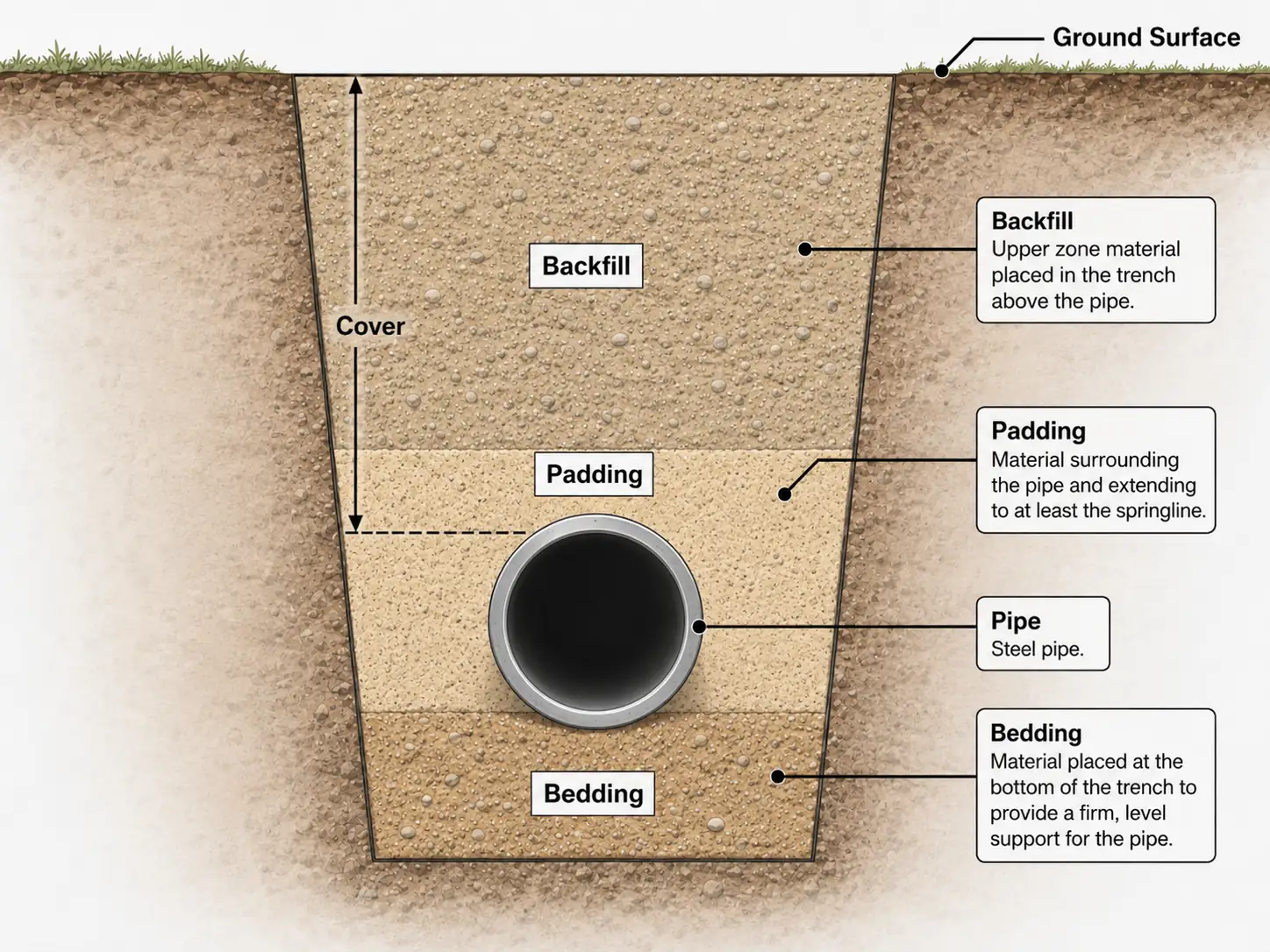
- Trench bottom: graded free of rock and debris so the pipe is uniformly supported — point loads on the pipe barrel and coating are what bedding exists to prevent.
- Padding: select fill (or screened native soil, often produced by padding machines) placed around and above the pipe to protect the coating; rock shield is an alternative where select material is scarce.
- Backfill and compaction: returned in lifts to limit future settlement of the trench line, with density requirements tightening under roads and structures.
- Trench breakers: sandbag or foam dams placed on slopes to stop the trench from becoming a french drain that erodes backfill and drains wetlands.
- Buoyancy control: in high-groundwater and wetland reaches, concrete weights, set-on weights, or geotextile saddlebags offset flotation — verified by a buoyancy calculation.
Groundwater Control: Dewatering and Well Point Systems
Wherever the trench bottom sits below the water table, groundwater becomes a construction problem in its own right. Seepage softens the trench bottom so bedding cannot be graded or compacted, and in fine sands and silts an upward gradient can produce a quick ("boiling") condition that turns the bottom fluid and undermines side slopes and shoring. Standing water floats the pipe string before backfill goes on, makes welding, coating repair, and inspection impossible, and turns returned backfill into an uncompactable slurry that guarantees future settlement. OSHA Subpart P treats accumulated water as an excavation hazard as well: work in a wet trench is prohibited unless the water is controlled and the protective system is designed for the condition. The consequence for planning is that groundwater has to be lowered before excavation reaches it — pumping out a trench that has already flooded does nothing about the saturated, unstable ground around it.
For open sumps and pumps to keep up, inflow must be modest; in permeable granular soils the standard solution is a well point system. Small-diameter screened wells are jetted into the ground at close spacing — typically a few feet apart — along one or both sides of the trench line, connected by riser pipes to a common header under vacuum. Operated ahead of the excavation, the system pulls the water table down below trench bottom so the ditch is opened in stable, workable ground. Because the system works by suction lift, a single stage is limited to roughly 15 feet of practical drawdown; deeper trenches require staged well points or deep wells with submersible pumps. Dewatering also carries a permitting tail: the discharge is regulated, usually requiring settlement through filter bags or basins and sediment controls before release, and high-volume dewatering near wetlands or water wells can itself trigger review. Route reaches with shallow groundwater are best identified during design — from water-well records, soils data, and wetland mapping — so dewatering shows up in the bid, not as a claim.
The Trench Is a Regulated Excavation: OSHA Subpart P
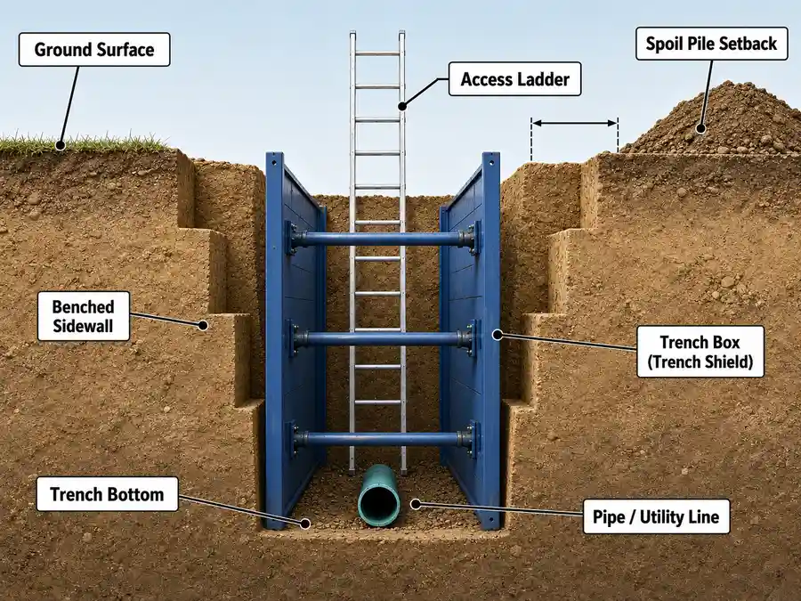
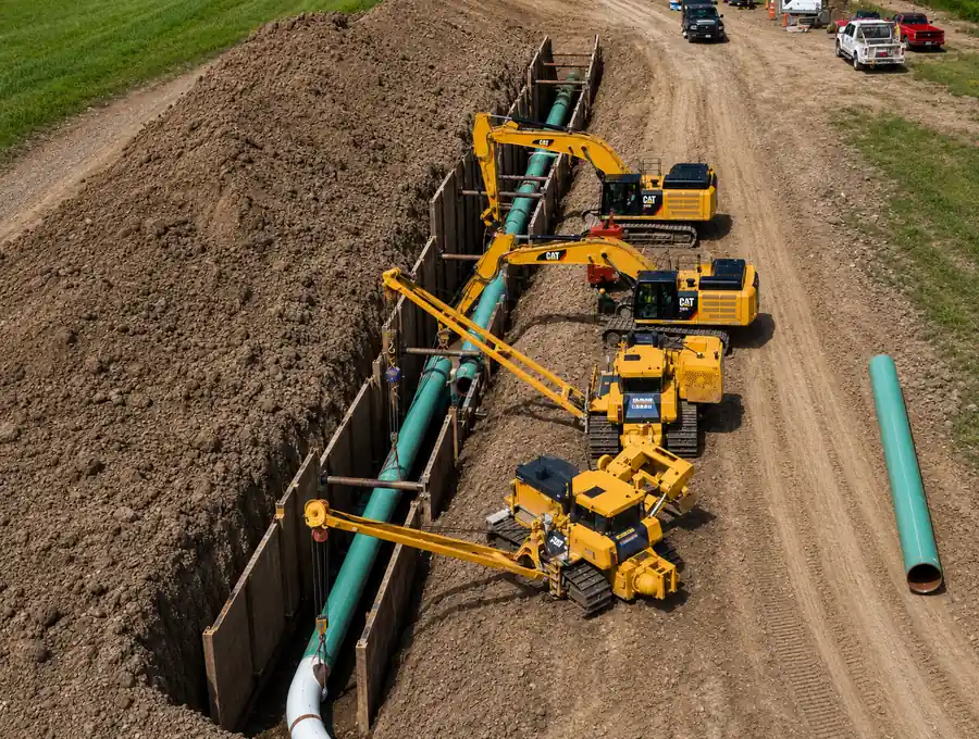
Any trench five feet or deeper must be protected against cave-in under OSHA 29 CFR 1926 Subpart P — by sloping or benching to angles set by soil type, or by shoring or trench boxes — and a designated competent person must inspect the excavation daily and after every rain. Spoil must be set back at least two feet from the trench edge, ladders or ramps are required within 25 feet of workers in trenches four feet or deeper, and atmospheric testing applies where hazards are possible. Trench collapses remain among the deadliest recurring accidents in heavy construction.