Pipeline Engineering Calculations, Open Cut & Trenchless Installation Planning

Pipeline Planning Toolbox by SubTerra Pipeline Engineering.

  • Design smarter crossings. Plan and engineer horizontal directional drilling (HDD), trenchless installation, and open-cut crossings — every design built on a comprehensive 50-state mapping engine.
  • See every constraint in one place. Overlay water wells, geotechnical boring logs, geology and lithology, soils and depth to bedrock, wetlands, flood zones, contaminated sites, oil & gas wells, pipelines, power and telecom transmission lines, railroads, levees, parcels with owner lookup, and protected lands and more.
  • Get a head start on permitting. An automated permitting analysis engine reads the layers your route crosses and flags the permits each crossing is likely to trigger — turning site constraints into progress on your permit package.
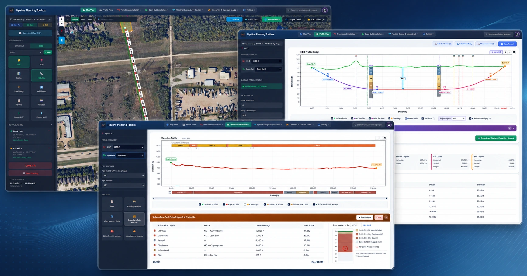
SubTerra Pipeline Engineering application — map interface with data layers

Powered by authoritative federal & state data sources

USGSElevation, Geology, Hydrography & Karst
FEMAFlood Zones, Levees & Building Footprints
USFWSCritical Habitat & Endangered Species
NWINational Wetlands Inventory
EPASuperfund, RCRA & Brownfields Sites
USACELevees (NLD) & Dams (NID)
U.S. DOT / EIAOil, Gas & Product Pipelines
PHMSANational Pipeline Mapping System (NPMS)
FRA / BTSNorth American Rail Network
U.S. CensusHighways & Tribal Lands (TIGER)
HIFLDPower Lines, Substations & Comm Towers
FCCRegistered Communication Towers
USDA NRCSSurface Soils (SSURGO)
USGS / MRLCNational Land Cover (NLCD)
NPSNational Register of Historic Places
BIATribal Reservations & Trust Lands

Why Pipeline Planning Toolbox?

SubTerra Pipeline Engineering's all-in-one HDD and open-cut design, assessment, and planning toolbox.

The Problem

Pipeline Engineers spend hours manually researching environmental constraints, utility crossings, flood zones, wetlands, and subsurface geology across dozens of separate government websites before they can even begin planning a bore or an open cut design.

The Solution

Pipeline Planning Toolbox brings together 60+ federal and state data layers into one unified, interactive map. Easily toggle layers, click on features for detailed insights, upload your own KML/KMZ alignments, and evaluate risks, environmental factors, and subsurface conditions in real time — powered by 30+ integrated pipeline engineering calculations.

Key Features

Everything you need for Horizontal Directional Drilling & Open Cut planning and environmental risk assessment — in one tool.

Environmental Layers

USFWS Critical Habitat with endangered species identification, NWI Wetlands with classification details, FEMA Flood Zones with zone type breakdown.

Infrastructure Crossings

Natural gas, crude, and petroleum pipelines from DOT/EIA, with operator data and HDD crossing warnings. Open-cut alignments get a full design pass: subsurface profiling at pipe depth, a 49 CFR §192.5 class location study over mapped building footprints, OSHA Subpart P trench protection, §192.179 block-valve spacing, and a BOM with pipe footage and elbow takeoff.

Subsurface Intelligence

USGS geologic maps, water well boring logs across all 50 states with lithology data and well completion reports.

Measurement Tools

Draw lines, polygons, and circles to measure distances, mark bore paths, and design TWS, ATWS, and easement footprints. Edit shapes with vertex add/remove, live color and thickness adjustments.

KML/KMZ Import

Import project alignments, bore paths, and survey data directly onto the map for instant overlay with all data layers.

Click-to-Identify

Click any highlighted area on the map to instantly see details: species name, flood zone type, well depth, publicly available pipelines, wetland classification, Karst Features.

Interactive Map — Every Crossing, Constraint & Permit Trigger on One Screen

60+ federal and state data layers — pipelines, rail & road crossings, power & telecom, buildings, levees, dams & waterways, renewables, water & wetlands, protected & sensitive areas, contaminated sites, soils & geology, geohazards, wells & borings, and land boundaries — sourced from USFWS, USFS, FEMA, EPA, USGS, NRCS, EIA, PHMSA, FCC, U.S. DOT (FRA/BTS), U.S. Census, USACE, NPS, and BIA, all accessible with a single click.

🛢️ Pipelines

NPMS Public Viewer

Direct link to the National Pipeline Mapping System public viewer.

PHMSA

Natural Gas Pipelines

Interstate and intrastate gas transmission lines.

EIA

Crude Oil Pipelines

Crude oil transmission pipelines by operator.

EIA

Petroleum Product Pipelines

Refined product and HGL transmission lines.

EIA

🚆 Rail & Road Crossings

Railroads

North American Rail Network with owner, trackage, and passenger flags.

FRA NARN

Major Roads & Highways

Interstates and primary roads requiring DOT right-of-way permits.

TIGER

⚡ Power & Telecom

Electric Transmission Lines

High-voltage lines with voltage class; flags AC interference risk.

HIFLD

Electric Substations

Substation locations with buried ground grids and duct banks.

HIFLD

Cellular / Comm Towers

FCC-registered cellular, broadcast, and microwave towers.

FCC

🏢 Buildings

Building Footprints

Structure footprints with occupancy class and address for setback screening.

FEMA USA Structures

Water Source — Fire Hydrants

Crowd-sourced hydrant locations for HDD water-supply planning.

OpenStreetMap

🛡️ Levees, Dams & Waterways

Leveed Areas

National Levee Database leveed areas; triggers USACE Section 408 review.

USACE NLD

Levee Embankments

Mapped levee embankment centerlines with stand-off requirements.

USACE NLD

Levees

FEMA-mapped accredited and provisional levees from the NFHL.

FEMA NFHL

Dams

National Inventory of Dams with owner, purpose, and hazard potential.

NID

Commercially Navigable Waterways

USACE National Waterway Network channels and commercial navigation routes.

NWN

🌬️ Renewable Energy

Wind Turbines

U.S. Wind Turbine Database locations, hub heights, and rated capacity.

USWTDB

Solar PV Facilities

U.S. utility-scale photovoltaic facility footprints and capacity.

USPVDB

💧 Water & Wetlands

Flood Zones

FEMA flood hazard zones including 100-year and 500-year floodplain boundaries.

FEMA NFHL

Wetlands

National Wetlands Inventory with Cowardin classification codes and wetland types.

NWI

Streams & Rivers

National Hydrography Dataset streams, rivers, and waterbody features.

NHD

USGS Stream Gauges

Active USGS streamflow gauging stations for hydrologic reference.

USGS

River Bathymetry

Links to USACE eHydro bathymetric surveys for navigable river crossings.

USACE eHydro

🦅 Protected & Sensitive Areas

Critical Habitat

Final and proposed habitat for threatened and endangered species; triggers ESA Section 7.

USFWS

Wild & Scenic Rivers

Federally protected river corridors; crossings require a §7(a) determination.

USFS

Protected Lands — State/Local/Tribal

State, local, and tribal protected areas with conservation status and management designations.

PAD-US

☢️ Contaminated Sites

Superfund Sites

EPA National Priorities List — the nation's most contaminated land and groundwater.

NPL

RCRA Corrective Action Sites

Hazardous-waste facilities under active cleanup with documented releases.

EPA

Brownfields

Formerly contaminated properties tracked in EPA's ACRES system.

EPA ACRES

🪨 Soils & Geology

Land Cover

NLCD 2021 land cover classification for surface and habitat context.

NLCD 2021

Geologic Maps

State Geologic Map Compilation — bedrock and surficial geology units.

USGS

Surface Soils

SSURGO soil map units with engineering and drainage properties.

SSURGO

⚠️ Geohazards

Karst Features

Mapped karst and soluble-rock terrain prone to voids and sinkholes.

USGS

Mines

Active, abandoned, and unknown-status mine locations.

USGS

🕳️ Wells & Borings

Water Wells

Well locations, depths, and lithology from 45+ state geological survey databases.

State Surveys / USGS

Oil & Gas Wells

Oil and gas well locations and status from FracTracker.

FracTracker

Geotechnical & Survey Borings

Geotechnical and survey boring logs for subsurface verification along the alignment.

Project Data

📍 Boundaries

Parcels

Statewide parcel boundaries for landowner identification.

State / County

Federal Lands

BLM, USFS, NPS, and DoD lands requiring right-of-way grants and NEPA review.

PAD-US

USACE-Owned Land

Corps Civil Works fee lands requiring real-estate outgrants and §408.

USACE

Historic Places

National Register sites triggering Section 106 cultural-resource review.

NRHP

Federal American Indian Reservations

Federal American Indian reservations requiring tribal consent and BIA ROW.

Census

Pipeline Engineering Calculations

30+ horizontal directional drilling (HDD) and pipeline engineering calculation modules built on ASME B31.4/B31.8, API 1102, 49 CFR 192, ASTM, and PRCI — for HDD design, trenchless installation, and validation.

Explore the calculators & engineering references →

Map & Profile

Map View

Interactive plan-view map of the pipeline and HDD alignment with overlayable environmental, cadastral, and utility data layers, satellite and USGS topo basemaps, KMZ import/export, and entry/exit placement with live station and coordinate readout.

References
  • ASCE MOP 108 — Pipeline Design for Installation by Horizontal Directional Drilling
  • OGC WMS/WFS data layer standards

Profile View

Vertical cross-section of the alignment showing entry and exit angles, design radius, tangent and curve segments, depth of cover, and soil stratigraphy from boring logs — with a station–elevation summary of every PC, PT, and tangent point.

References
  • ASCE MOP 108 — Pipeline Design for Installation by HDD
  • ASTM F1962 — Use of Maxi-HDD for Placement of PE Pipe

Trenchless Installation

Pilot Hole Geometry Verification

Example Report

Validates as-drilled pilot-hole curvature, bend angles, and minimum radius against design tolerances to confirm the path is drillable and within allowable pipe strain limits.

References
  • ASCE MOP 108 — Pipeline Design for Installation by HDD
  • ASTM F1962 — Use of Maxi-Horizontal Directional Drilling for Placement of PE Pipe

Minimum HDD Length

Calculates the minimum surface-to-surface HDD length needed to reach target depth-of-cover given entry/exit angles and minimum allowable bend radius.

References
  • ASCE MOP 108 — Pipeline Design for Installation by HDD

HDD Water Use

Example Report

Estimates the total water and drilling-fluid volume required for the pilot hole and reaming passes based on borehole geometry, soil type, and mud-recycling efficiency for water-sourcing and disposal planning.

References
  • ASCE MOP 108 — Pipeline Design for Installation by HDD
  • API RP 13B-1 — Field Testing Water-Based Drilling Fluids

Operational Stresses (Steel)

Example Report

Combined axial, bending, and hoop stresses on the in-service pipe after HDD installation, including residual curvature and external overburden loading.

References
  • ASCE MOP 108
  • PRCI PR-227-9424 — Huey, Hair & McLeod (1996), Installation Loading and Stress Analysis of Pipelines Installed by HDD

PE Pipe HDD Stress Analysis (Plastic)

Example Report

Evaluates tensile pull-back load, bending strain, and external-pressure collapse for polyethylene (PE) pipe installed by HDD.

References
  • ASTM F1962 — HDD Placement of PE Pipe
  • PPI TR-46 — Guidelines for Use of MDPE/HDPE in HDD

HFIR Analysis

Example Report

Predicts maximum allowable downhole annular fluid pressure to avoid hydraulic fracture of surrounding soil and inadvertent returns (frac-out) through overlying strata.

References
  • Delft / Luger–Hergarden method (1988)
  • Staheli et al. — PRCI guidance on HDD hydrofracture
  • ASCE MOP 108

Bentonite Yield Calculator

Estimates drilling-fluid yield (bbl per 100 lb) for bentonite-based mud given mix ratios, water chemistry, and viscosifier content for pilot-hole and reaming passes.

References
  • API Spec 13A — Drilling Fluids Materials
  • API RP 13B-1 — Field Testing Water-Based Drilling Fluids

Buoyancy Control Analysis

Determines whether the pipe floats in the surrounding fluid before any weighting is applied — buoyant force versus steel, coating, and product weight — and reports the buoyancy ratio and net uplift per foot that the weighting design must overcome.

References
  • PRCI HDD buoyancy guidance
  • ASCE MOP 108

Continuous Concrete Coating

Sizes the continuous concrete weight-coating thickness needed to hold the pipe down to a target negative buoyancy in flooded bores, wetlands, and submerged crossings, from pipe geometry, coating density, and fluid unit weight.

References
  • ISO 21809-5 — External concrete coatings for pipelines
  • ASCE MOP 108

Weight Spacing

Example Report

Calculates the center-to-center spacing of set-on or bolt-on concrete river weights required to hit a target buoyancy ratio, given weight mass, unit weight, and the net uplift on the coated pipe.

References
  • PRCI HDD buoyancy guidance
  • ASCE MOP 108

Settlement Analysis

Example Report

Estimates ground-surface settlement above the bore due to volume loss and soil disturbance along the HDD alignment.

References
  • Peck (1969) — empirical settlement trough method
  • ASCE MOP 108

Pull Force & Installation Stresses

Example Report

Predicts the pull-back tension required to install the pipe string and the resulting axial + bending stresses, accounting for fluid drag, capstan friction, borehole friction, and buoyancy.

References
  • ASCE MOP 108
  • PRCI PR-227-9424 (Huey et al., 1996)

Max Allowable Pullback Force

Example Report

Determines the limiting pull-back tension and minimum allowable bend radius that keep combined installation stresses within code limits for steel or PE pipe.

References
  • ASCE MOP 108
  • ASTM F1962 (PE pipe limits)
  • PRCI PR-227-9424

Pullback Cradle Supports Span

Example Report

Spacing of roller cradles along the staging/pullback side so the pipe string’s bending stress and sag stay within allowable limits prior to bore entry.

References
  • ASCE MOP 108

Piping Spacing for Roller Supports

Example Report

Maximum distance between pipe supports based on allowable bending stress, deflection, and self-weight plus contents for aboveground or temporary support conditions.

References
  • MSS SP-69 — Pipe Hangers and Supports
  • ASME B31.1 Appendix — Recommended Support Spacing

Auger Bore Thrust & Stresses

Example Report

Computes jacking thrust force and resulting casing stresses for horizontal auger-bore installations, including soil-skin friction and end bearing.

References
  • ASCE MOP 106 — Horizontal Auger Boring Projects
  • ASTM F1962 (trenchless design framework)

Trenchless Technology Overview

Reference overview of trenchless installation methods — HDD, auger boring, microtunneling, and pipe ramming — with selection criteria by soil and site conditions.

References
  • ASCE MOP 108
  • ASCE MOP 106 — Horizontal Auger Boring Projects

Drilling Equipment Reference

Reference guide to HDD rig classes, mud systems, reamers, and downhole tooling by bore diameter and ground condition.

References
  • ASCE MOP 108

Soil Interpretation Guide

Reference for interpreting geotechnical boring logs, USCS soil classifications, and the parameters most relevant to trenchless design.

References
  • ASTM D2487 — Unified Soil Classification System
  • ASCE MOP 108

Open Cut Installation

Open Cut Installation

Evaluates earth (overburden) and live (traffic) loads on a buried pipe installed by conventional open-cut trenching, including bedding, deflection, and backfill conditions.

References
  • AWWA M11 — Steel Pipe: A Guide for Design and Installation
  • ASME B31.4 / B31.8 — buried pipe design criteria

Lowering In Place (API RP 1117)

Example Report

Evaluates bending, tensile, and combined stresses in a pipeline during lowering-in from the right-of-way into the trench, accounting for sag, hold-down positions, and sideboom spacing.

References
  • API RP 1117 — Movement of In-Service Pipelines
  • ASME B31.4 — Pipeline Transportation Systems for Liquids and Slurries
  • ASME B31.8 — Gas Transmission and Distribution Piping Systems

Pipeline Valve Spacing (PHMSA §192.179)

Checks mainline valve spacing against the maximum intervals PHMSA sets for each class location, so an operator can confirm sectionalizing-valve placement and blowdown provisions on a transmission line.

References
  • 49 CFR §192.179 — Transmission line valves
  • ASME B31.8 — Gas Transmission and Distribution Piping Systems

Pipe Specs Viewer

Searchable reference of standard line-pipe dimensions, wall thicknesses, weights, and grades for quick lookup during design.

References
  • API Spec 5L — Line Pipe
  • ASME B36.10M — Welded and Seamless Wrought Steel Pipe

Pipeline Design & Hydraulics

Pipe SMYS / Barlow's Calcs

Example Report

Checks hoop, longitudinal, and combined stresses against the pipe’s specified minimum yield strength (SMYS) per API 5L grade and design-factor limits.

References
  • API Spec 5L — Line Pipe
  • ASME B31.4 / B31.8 design-factor criteria

Gas Pipe Sizing

Sizes distribution and service piping for a required delivery load and allowable pressure drop, comparing candidate diameters and materials across low- and elevated-pressure sizing methods.

References
  • NFPA 54 / ANSI Z223.1 — National Fuel Gas Code
  • AGA Gas Engineering Handbook — Spitzglass and Weymouth relations

Gas Pipeline Hydraulics

Steady-state flow and pressure-drop analysis for gas transmission lines using the Panhandle A/B, Weymouth, and AGA fully-turbulent equations, with compressibility, elevation, and pipeline-efficiency corrections.

References
  • AGA — Steady Flow in Gas Pipelines
  • ASME B31.8 — Gas Transmission and Distribution Piping Systems

Control Valve Sizing

Determines the required valve flow coefficient (Cv) for gas or liquid service and screens the operating range for choked flow, critical pressure drop, and excess velocity or noise.

References
  • ISA-75.01.01 / IEC 60534-2-1 — Control valve sizing equations
  • ISA-75.17 — Control valve aerodynamic noise prediction

Blowdown Time

Estimates the time to depressurize a pipeline segment through a blowdown valve or vent stack from segment volume, initial and target pressure, gas properties, and vent size.

References
  • ASME B31.8 — Gas Transmission Piping
  • API Std 521 — Pressure-Relieving and Depressuring Systems

Blowdown Thrust Force

Example Report

Calculates reaction-thrust force generated by venting pressurized gas through an open end during blowdown; used to size restraint, thrust blocks, and personnel exclusion zones.

References
  • ASME B31.8 — Gas Transmission Piping
  • API Std 521 — Pressure-Relieving and Depressuring Systems

Crossings & External Loads

Calculates earth-load and cyclic live-load (wheel / rail) stresses for cased and uncased pipelines crossing highways and railroads.

References
  • API RP 1102 — Steel Pipelines Crossing Railroads and Highways

Uncased Pipeline Crossing

Example Report

Checks barrel, circumferential, and longitudinal stresses for uncased crossings under roadway/rail loading with appropriate impact and depth-of-cover effects.

References
  • API RP 1102
  • ASME B31.8 (for gas) / ASME B31.4 (for liquids)

Wheel Load Analysis

Example Report

Evaluates pipe stresses from highway vehicle wheel loads, including dynamic impact factor and load-distribution through cover soil.

References
  • API RP 1102 (highway loading)
  • AASHTO LRFD Bridge Design Specifications

Track Load Analysis

Example Report

Evaluates pipe stresses from rail live loads (Cooper E-80 or equivalent) beneath railroad tracks, including impact and load cycle effects.

References
  • API RP 1102 (rail loading)
  • AREMA Manual for Railway Engineering

Testing

Minimum Hydrotest Pipeline Bend Radius

Example Report

Minimum allowable bend radius during hydrostatic testing that keeps combined hoop + longitudinal stresses below the code-specified percent of SMYS.

References
  • ASME B31.4 — Liquid Pipelines
  • ASME B31.8 — Gas Pipelines

Hydrotest Water Volume Required

Example Report

Test-pressure determination, fill-volume estimation, and static-head corrections across the pipeline elevation profile for hydrotest water sourcing and disposal planning.

References
  • API RP 1110 — Pressure Testing of Steel Pipelines
  • ASME B31.4 / B31.8 test-pressure requirements
  • 49 CFR §192.505 / §195.304

Hydrostatic Pressure & Volume Change

Example Report

Relates pressure change during the hold period to air entrainment, temperature drift, and leak volume to distinguish thermal effects from real leaks.

References
  • API RP 1110
  • ASME B31.8 Appendix N — Temperature / pressure relationships for hydrostatic testing

Hydrotest Potential Impact Radius (PIR)

Potential Impact Radius (PIR) around a gas pipeline defining the area of significant thermal impact from a full-bore rupture, used in integrity management and HCA classification.

References
  • ASME B31.8S §3.2 — Managing System Integrity of Gas Pipelines

Frequently Asked Questions

Common questions about the HDD planning tool and environmental assessment features.

What is the Pipeline Planning Toolbox and who is it for?

It's a cloud-based pipeline engineering platform for HDD designers, pipeline engineers, utility & energy developers, and construction/EPC teams. It replaces the patchwork of spreadsheets, desktop tools, agency GIS portals, and reference lookups with 30+ calculation modules and an interactive map of 45+ live data layers — energy, utility, transportation, environmental, subsurface/geotechnical, and land-ownership data — plus automated permit screening of the corridor. Everything attaches to a single alignment, all in one browser-based app.

What engineering standards and calculations does the toolbox cover?

The toolbox includes 25+ calculation modules built on industry-governing codes (ASME B31.4/B31.8, API 1102, 49 CFR 192, ASTM, PRCI, etc). Coverage spans Pipe Design and SMYS, installation and operational stresses for HDD crossings, Pullback Force, HDD Bore Geometry, Highway and Railroad Crossings, Hydrotest Analysis, HFIR (various methods), Settlement Analysis, and more — so you can take a project from planning through verification in one place.

What geospatial data is available on the map?

The map integrates 60+ external data sources: satellite/topo basemaps (Google, ESRI, Bing, USGS), pipeline layers (EIA natural gas, crude oil, HGL), FEMA flood zones, USFWS critical habitat and NWI wetlands, USGS streams and geology, real-time USGS elevation profiling along your bore path, and water-well databases from 45+ states. You can also import KML/KMZ alignments and auto-detect road, rail, and stream crossings along the path. You can also export coordinates to Excel or generate a KMZ file for your HDD or open-cut design, allowing you to view it directly in Google Earth.

How are my projects saved and can I generate reports?

Projects are saved to your account in the cloud with autosave across every analysis, so you can pick up on any device. Each module produces a professional PDF engineering report generated directly in your browser — stamped with project details, inputs, calculated values, and charts — ready to attach to permits or deliverables.

Start Your Next HDD or Open-Cut Project With Us

All the data, calculations, and reports you need. Zero setup. 7-day free Expert Tier trial.

Start Free Trial — 7 Days